Product Application Notes – Millimeter-Wave Radar Subsystems
Applications:
Millimeter-wave radars serve a wide range of applications such as remote sensing, safety, and measurement. In most applications, millimeter-wave sensors are superior to microwave- and infrared-based sensors. Firstly, millimeter-wave radars offer better range resolution than lower frequency microwave radars. Secondly, they penetrate fog, smoke, and other obscurants much better than infrared sensors.
To illustrate, here are some commonly used millimeter-wave radar subsystems.
- Automobile collision warning sensor
- Autonomous cruise control
- Robotic vision
- Surveillance – air defense, sniper/artillery location-tracking
- Altimeters and height/depth measurement
- Missile guidance and tracking
- Speed and range measurement for industrial uses
- Industrial depth measurement in hostile environment
- Severe weather studies and measurement
- Clear air turbulence/wind field measurements
- Wide area traffic monitoring and control
- Intrusion detection
- Aircraft collision warning/obstacle detection system for helicopters, Unmanned Aerial Vehicle (UAV), Unmanned Surface Vehicle (USV)
- Harbor monitoring and navigation guidance
- Imaging
- Vision/sensing in adverse weather/environment
- Presence/motion sensors for automated systems
- Safety and security devices
Millimeter-Wave Radars Description
Generally, millimeter-wave radars are categorized as either pulsed or continuous wave (CW). There are several specific modes of operation.
Pulsed Radars
- Coherent Pulsed
- Doppler/Moving Target Indicator
- Incoherent Pulsed
- Pulse Compression (FM/PM/Polarization diversity)
CW Radars
- Doppler
- Frequency Modulated (FMCW)
- Phase Modulated and Multi-frequency waveform
In any case, the radar determines the size, characteristics, range, and velocity of the object or scene by measuring the characteristics of the return signal after reflection/scattering from it. Specifically, the amplitude, spectral contents, and return signal’s arrival time provide the necessary information.
This table shows a basic comparison of the two types or modes.
| Requirement or Feature | CW Radars | Pulsed Radars |
| Hardware Complexity | Simpler | More Complex |
| Short range target Detection | Superior | Better for longer ranges |
| Moving target discrimination | Inherent capability. Easy to realize. | Not trivial to implement. Requires sophisticated signal processing. Doppler frequencies that are multiples of pulse repetition frequency are difficult to detect/measure. |
| Target range Discrimination | Moderate | Superior due to narrow pulse width and other techniques |
| Transmitter-Receiver Isolation | Moderate (20-25 dB) for mono-static (single common antenna)configuration. High (>50 dB) for bi-static antenna configuration. | Inherently High |
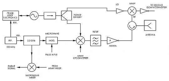
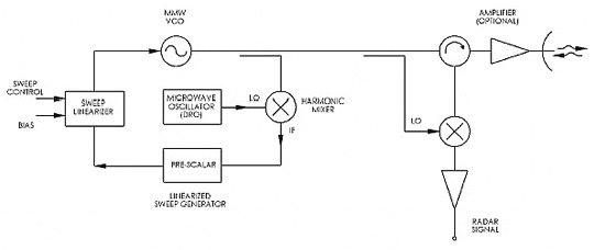
The figures below show examples of radar architecture. The most important element in any radar is the transmitter source for the equipment. Of note, the transmitter source often additionally serves as the local oscillator source. The transmitter signal can be CW, pulsed, or modulated with one of many specific radar waveforms. The received signal can be pre-amplified using a low-noise amplifier for enhanced sensitivity or range. Then the radar receiver or downconverter produces the appropriate intermediate frequency or baseband radar return signal. In turn, this is amplified, filtered, and processed by the radar signal processor to generate the information or image.
Figure 1(a) Homodyne Radar

Figure 1(b) Heterodyne Radar with UPC Upconverter Signal Scheme

Figure 1(c) FMCW Radar

Operation and Typical Performance Characteristics
Pulsed radars are generally coherent radars, using a stable lower frequency source as the reference signal. They normally use a single antenna (mono-static configuration) for transmit and receive functions. A modulator creates the required radar pulses and waveform as well as any necessary frequency agility. The transmitter module generates a short pulse of millimeter wave that is fed to the antenna. This pulse may be from a few microseconds to a few nanoseconds. Finally, the return signal is routed to the receiver by a duplexer such as a circulator. When necessary, receiver protection and limiting functions are incorporated in the receiver’s front end.
Low phase noise contents of the transmitter signal and of any local oscillator used in the receiver is essential to the operation of the radar. Depending on the range, sensitivity and resolution, and other requirements, the phase noise plays a vital role in determining the radar’s capabilities.
CW and FMCW radars typically transmit a continuous wave signal, which could be frequency modulated or chirped/swept. When frequency modulated, the linearity and bandwidth of the sweep is critical in determining the accuracy and the resolution of the radar. An FMCW radar can be configured as either mono-static or bi-static (single or separate antenna for transmit and receive functions). The local oscillator signal in this type of radar is generally the same as the transmitter signal. It is derived by splitting the power from the radar’s master source.
QuinStar Products Used
- Amplifiers (Low Noise, Power)
- Antennas
- Balanced Low-Noise Broadband Mixer
- Detectors
- Feed Horns
- Frequency Multipliers
- Microwave (IF) Amplifiers
- Oscillators (Gunn Diode Oscillator, QTM from 18-150 GHz)
- Phase Locked Sources and Electronics
- Power Dividers/Hybrids (Short Slot Coupler, Matched Hybrid Tee, Directional Couplers)
- Switches (pin, electromechanical)
