QuinStar Technology Inc.’s engineering team establishes the MMIC Test Lab for wafer testing and RF module evaluation in a class 10k cleanroom (Figure 1) at QuinStar’s headquarter in Torrance, California.
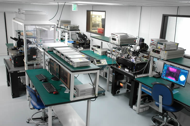
Figure 1. The MMIC Test Lab for wafer testing and RF module evaluation consists of three probe stations supported by the State-of-the-Art microwave & millimeter wave equipment in a class 10k cleanroom.
With the purpose of R&D and pilot production, this lab provides all the services required to meet the most stringent quality requirements of MMIC testing and device/component characterization in microwave-millimeter wave frequencies, with the support of resources available in-house:
- Know-how of QuinStar’s microwave experts
- Test and Measurement equipment
- Environmental Testing Facilities
- Machine Shop test fixture fabrication and Assembly Capability
- Custom Waveguide fabrication
Typical test equipment and accessories to support the testing work include the following:
- Anritsu MS4647B VNA, 70kHz to 70GHz with Broadband frequency extender up to 145GHz
- Spectrum analyzer up to 50GHz
- Oscilloscopes
- Digital multimeters
- DC power supplies up to 30V/4A,
- Signal synthesizer up to 50GHz
- QuinStar’s power amplifiers
- QuinStar’s frequency convertors
- Waveguides, WG adaptors, attenuators, couplers, high power terminations, etc.
- Power sensors (for coaxial and waveguide)
- ESD safe PVC nitrogen regulated desiccators for wafer storage
Three probe stations are set up to perform MMIC testing in a variety of test configuration and criterions in millimeter wave frequencies.
Detail description of the probe stations is presented in the following sections.
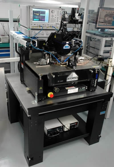
Figure 2. Summit 12KB Semi-automatic on-wafer probe station that provides on-wafer probing capability in both CW and pulsed modes.
Station 1 – Semi-Automatic On-Wafer Probe Station
The test station setup (Figure 2) provides on-wafer probing capability in both CW (145 GHz max.) and pulsed modes (70GHz max.). Equipped with DC pulsers and RF pulse modulation, the test system can synchronize the DC and RF stimulus with a minimum pulse width of 200 ns, and DC level up to 250V/30A. Typical measurement setup and results are shown in Figure 3.
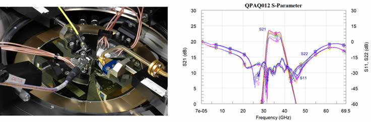
Figure 3. On-wafer probing in CW and pulsed modes are provided for MMIC evaluation and device characterization up to 145 GHz (left). A Ka-band MMIC amplifier is measured on-wafer in pulse-mode. Sample S-parameter data are obtained from 700 KHz to 69.5 GHz (right).
Equipment Features:
- Maury Microwave’s AMCAD PIV system with FW interface to Anritsu VNA, controlled by IVCAD and IQSTAR for pulsed RF/DC s-parameter measurements up to 70GHz
- FormFactor Summit 12KB semi-automatic probe station with custom adaptive plates for all wafer sizes
- GGB and Cascade Microtech GSG RF probes 100µm to 200µm pitch, coaxial and waveguide
- RPP304 RF probe tip holders and MPH DC probe card holders
- TMC gimbal piston vibration isolation table
Station 2 – Semi-Automatic Thermal Probe Station
The thermal probe station (Figure 4) is capable of on-wafer probing with (high) temperature control. This semi-automatic probing system is equipped with a thermally insulated chamber and low-profile card holders targeting for MMIC production test, from 20 to 300 degree Celsius.
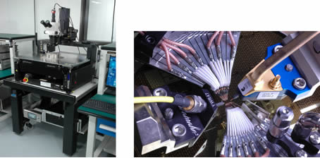
Figure 4. The Semi-Automatic Thermal Probe Station (left) provides multiple RF inputs in a down-converter die evaluation where temperature control up to 300°C is available (right).
Equipment Features:
- FormFactor Summit 12K semi-automatic probe station with microchamber and 200mm hi-isolation, thermally controlled chuck (-60 – 300°C, Ni)
- Summit Thermal System, air-cooled, +20 – 300 °C (TS-412-05T)
- Velox digital camera package with control software (Velox 3.1)
- Positioner, RF & DC, Summit (RPP304 and RPP210)
- GGB and Cascade Microtech GSG RF probes 100µm to 200µm pitch, coaxial and waveguide
- RPP304 RF probe tip holders and MPH DC probe card holders
- TMC gimbal piston vibration isolation table
Station 3 – Manual Power Probe Station
To reduce thermal effects in power testing, this probe station (Figure 5a) provides a low temperature chuck that can effectively dissipate heat generated by the DUT, and extract the ultimate performance of the power device. Supported by the Temptronic (TP3000A) refrigeration system (Figure 5b), the probe station is capable of characterizing devices at low temperatures where chuck temperature can be lowered down to -65°C.
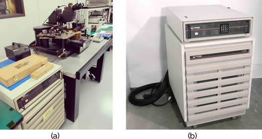
Figure 5. (a) The manual Power Probe Station includes high power RF probes and a thermally controlled chuck supported by the Temptronic refrigeration system, (b) Temptronic TP3000A chuck temperature controller provides on-wafer probing in low temperature down to -65°C.
Equipment Features:
- Manual probe station with thermally controlled chuck for high power tests
- Temptronic TPO3000A-2100-1 ThermoChuck System, -65°C to 200°C
- High power 50GHz RF probes from GGB and Cascade Microtech can handle up to 8W of power in coaxial and/or waveguide environment
- TMC gimbal piston vibration isolation table
Future Plans for Wafer Probe Testing
QuinStar is planning to add load-pull tuners (20 to 110 GHz) to the test set by the 2nd quarter of 2022. When configured with the load-pull tuners, the probing test set will provide real measurement of the non-linear behavior of a device across the full impedance plane. As a result, the load-pull data will facilitate engineers to obtain design solution with great accuracy and deliver millimeter-wave products of State-of-the-Art performance, a great thrust to new product development and company revenue.